Serial Experiments Anne - Part 1
by Anne Macedo

I love Serial IO and UART ports. I mean, they are so basic: send bits at a specific rate, connect tx and rx, read bits at a specific rate and then BAM, you have a TTY, you have logs.
However, if timing (or voltage) is not precise, things take a turn to the worse.
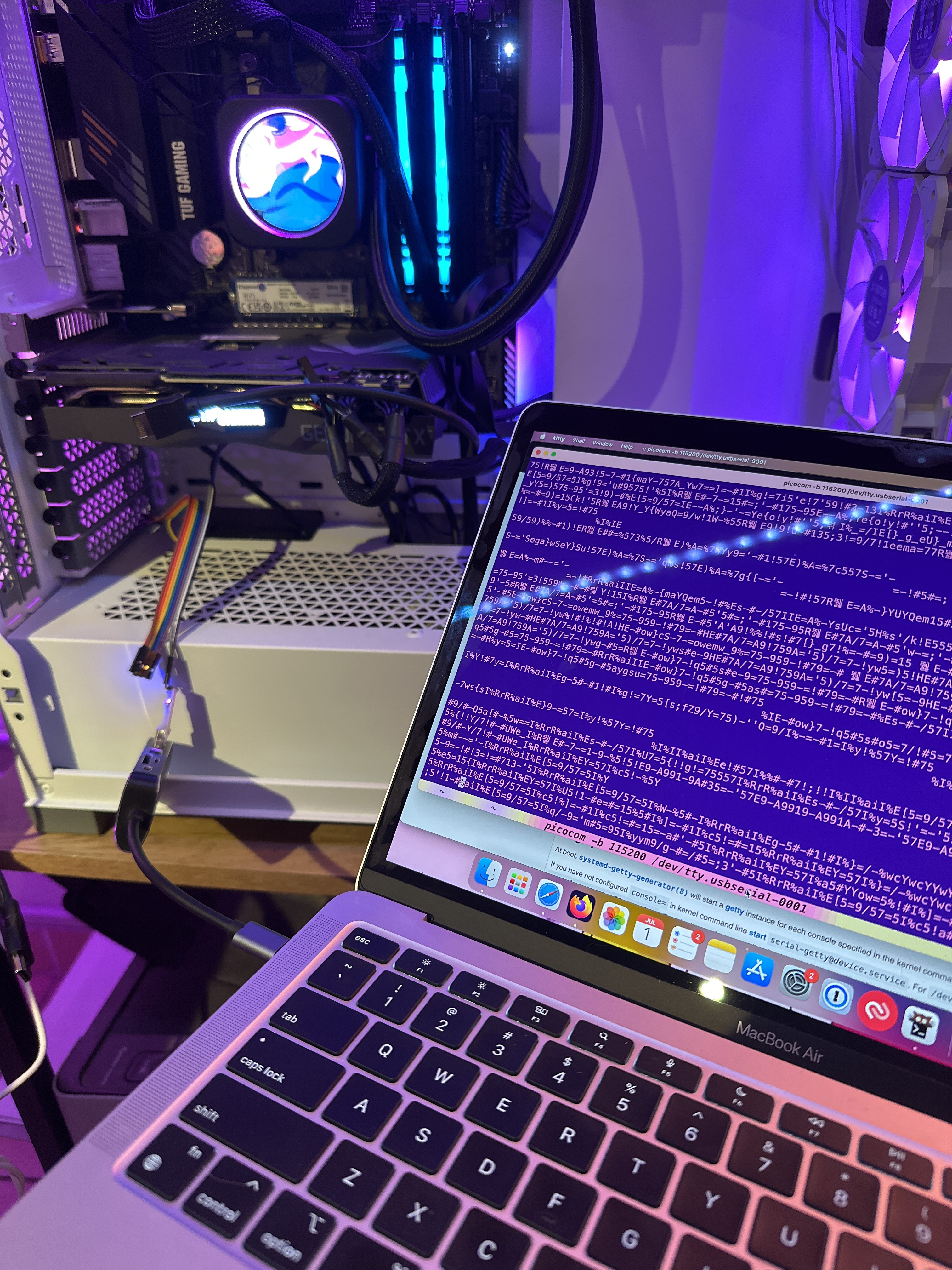
I’m currently thinking about a project where I use the COM port of my motherboard to send the serial logs to an FPGA, which receives these logs and renders them on a display. I kind of like doing things headless while I’m on my Mac and I usually prefer to do things via SSH, but I also want to have the feedback of the serial port.
In order to test things before the FPGA arrives, I wanted to use a 5V USB to TTL to read the logs from my 12V COM port. Nothing fried lol.
It worked, but not consistently… and this is so annoying.
BTW, I needed to add a serial console to the kernel command line. More here [2].
console=ttyS0,115200
This will allow you to have a serial TTY on /dev/ttyS0 at a baud rate 115200.
Analyzing stuff with a Logic Analyzer
Checking some signals in the logic analyzer, I saw the inverse measurement is 50khz for some bits. Some others are showing 25khz.
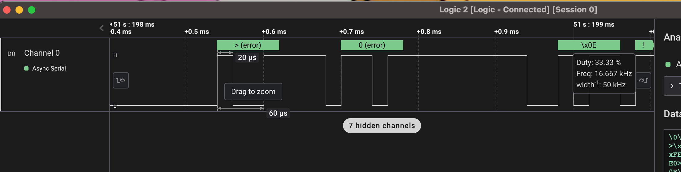
Things were looking wrong… I’ve increased the capture to 24MS/s and the bits from the 115200 baud rate were showing… but still had framing errors.
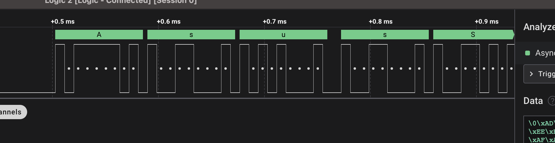
So! I decided to invert the signal and AAAAAAASUS!
It was inverted all along… how do I invert this signal to my USB to TTL? It was probably working sometimes because of USB-C or something.
Seems like my CP2102 doesn’t support inverting the signal, so I’m buying an FTDI.
I bought an FTDI… it didn’t change anything. I could actually invert the bits on the FTDI, but for some reason I couldn’t
reprogram it with FT_Prog.
What actually happens is this:
The COM port on my motherboard runs on RS232 – where it idles in +12V and every bit is -12V. TTL, on the other hand, idles on 0V and every bit is 5V. That’s why the signal was inverted!
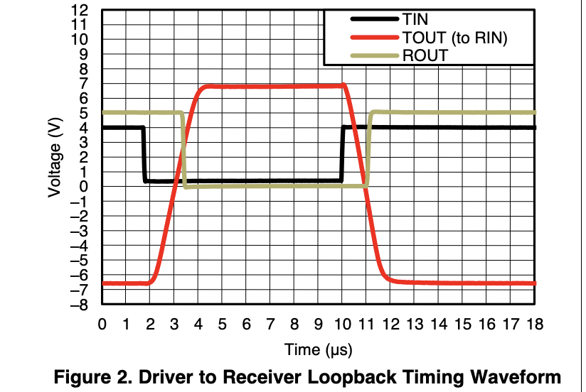
After spending a long time trying to understand it, and discussing with folks from the Hardware Hacking group, I decided to buy a MAX232.
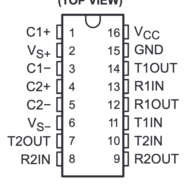
This chip translates RS232 to TTL logic, inverting the signal!
After beating my head a lot, things got quite easy. Datasheet is on [1].
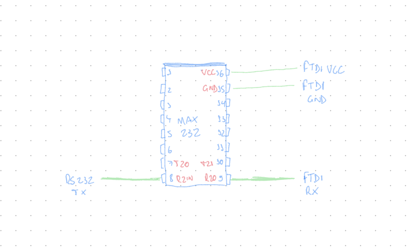
Basically, if I want to translate RS232 to TTL, this is the logic:
COM Port Tx (RS232) -> MAX232 R2IN pin -> MA232 R2OUT pin -> FTDI Rx
And the TTL Rx to RS232 - which I didn’t bother so much:
FTDI Tx -> MAX232 T2IN -> MAX232 T2OUT pin -> COM Port Rx (RS232)
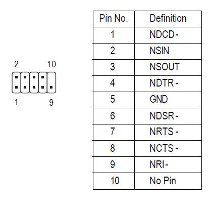
The COM Rx pin is the NSIN (pin 2) and COM Tx pin is the NSOUT (pin 3).
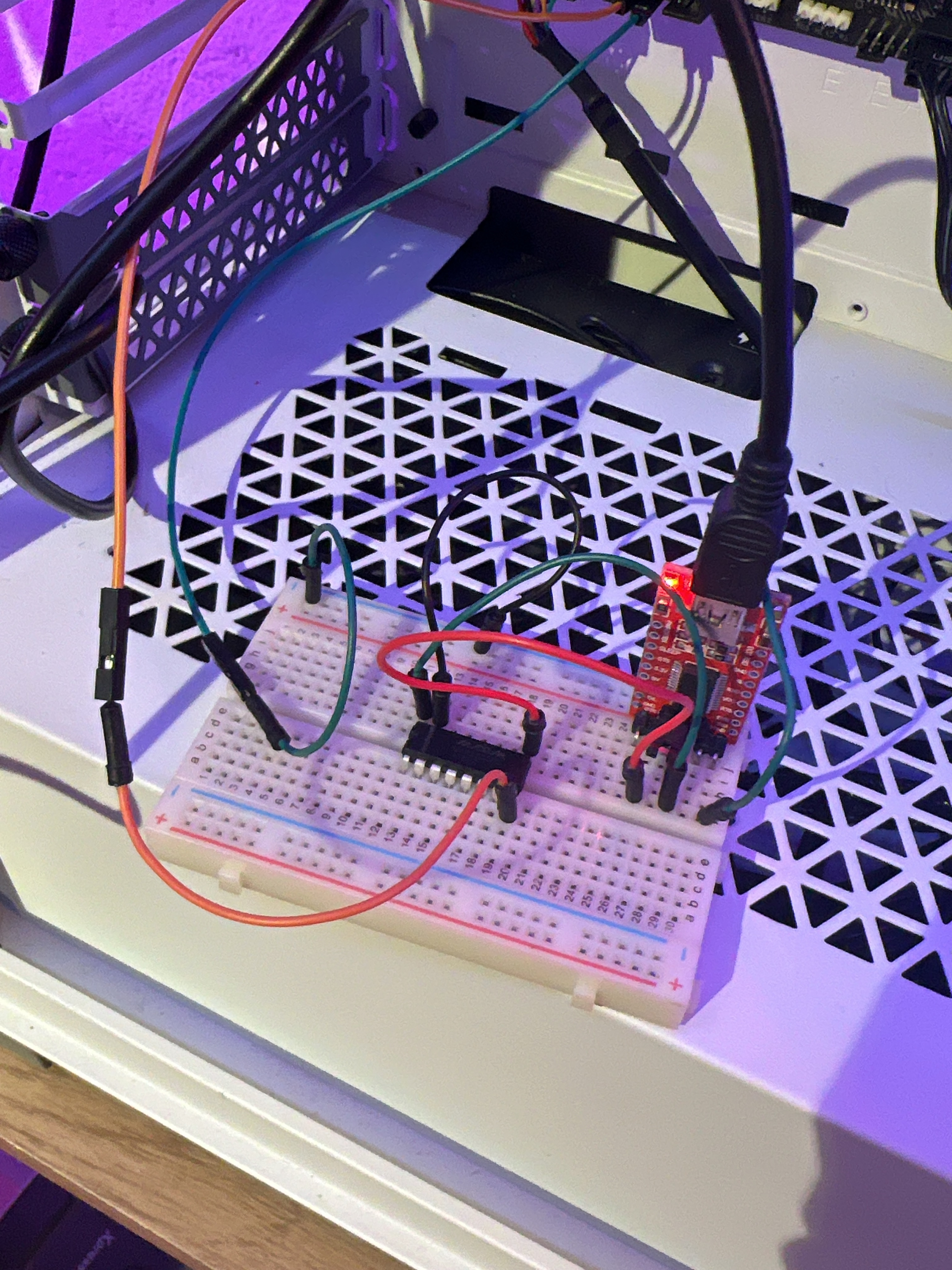
I plugged it all and the logic was still wrong… what am I missing?
Okay! So, it idles at 5V… where does it get this voltage? Air? No! VCC!
So I plugged the FTDI VCC to the MAX232 VCC and VOILÁ! Serial Logs!
Next steps
As I mentioned, now I have the circuit for translating RS232 to TTL. Next time, I’ll need to find out how to program the FPGA to:
- Be able to receive signal from UART
- Turn this signal into pixels
- Send these pixels to the LCD
But we’ll talk about it next time :).
References
[1] MAX232 Datasheet
tags: hardware - serial - uart